
Time Delay Relay Module V2
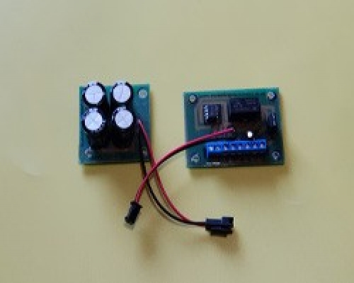
This module uses a 555 timer chip to delay sending a short trigger pulse once the relay has been activated. Upon activation (Momentary trigger via a push button switch for example) the relay will disconnect power for the primary output, wait a period of 0.5 – 8 seconds and then send a short 0.5-8 second trigger pulse to the secondary output before resuming power back to the primary output.
Board Size 70mm x 50mm
Power Bank Size 50mm x 50mm
Please note that PCB Pillars / Standoffs will be required for the circuit board. These fit into the 4 pre drilled holes of the circuit board. We have varies types available in our store PCB Pillars / Standoffs
Item number
Data Sheet
Product Name
Price
Add to Basket
Time Delay Relay Module V2 Wiring Instructions
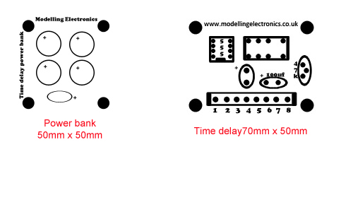
- Terminal 1: Negative secondary trigger pulse output
- Terminal 2: Positive secondary trigger pulse output
- Terminal 3: Negative primary output
- Terminal 4: Positive primary output
- Terminal 5 and 6: push button switch to trigger
- Terminal 7: Positive supply voltage
- Terminal 8: Negative supply voltage
This module requires a power bank connected via the cable in the center of the board. This power bank is then charged via the momentary action of the trigger switch. Once the module has been activated via the momentary push button switch the power bank charges, it is this charge that then holds power for your delay and trigger pulse of up to 8 seconds to the secondary output.
The time delay can be adjusted via the variable POT fitted to the right hand side of the module. The time of the trigger pulse depends on the time of the delay, the shorter the delay the longer the trigger pulse. The longer the delay the shorter the trigger pulse.
To adjust the time delays insert a small screwdriver into the center of the variable POT and turn fully clockwise. This will set the module timer to the shortest delay.
To extend the delay turn back (anti-clockwise) the variable POT in very small increments and re-test the delay. The variable POT can only be turned one third max anti-clockwise or the device will not function. If this happens turn the variable POT clockwise in small increments until the device starts to function again.
This module can function with a DC power supply of 9-15v only. The primary and secondary outputs provide a voltage equal to that of the supply voltage.