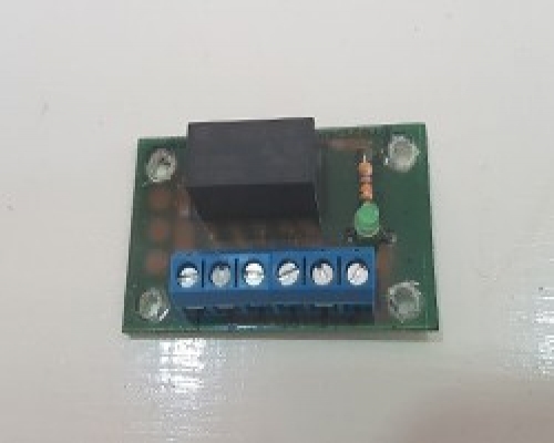
Reverse Polarity Switch Module
This is a compact reverse polarity switch module and can be used to change the polarity of the output terminals 5 and 6. Most common uses are to change the direction of a DC Motor.
Once the control voltage (Terminals 1 and 2) have power supplied to them the relay is activated and the output terminals of 5 and 6 will then change polarity.
The terminals 3 and 4 are the input voltage for the module and can take a max 1A 125VAC/2A 30VDC, the output voltage is fed from this input voltage The output will always have an active state, if the relay is off this will be the same polarity as the input voltage and when the relay is on the polarity will be the reverse of the input voltage.
Please note that PCB Pillars / Standoffs will be required for the circuit board. These fit into the 4 pre drilled holes of the circuit board. We have varies types available in our store PCB Pillars / Standoffs
| Control power supply | 5v or 12v DC |
| Feed input | 1-30v DC/1-125v AC |
| Output Voltage | 1-30v DC 2A / 1-125V AC 1A (Depending on the feed input voltage) |
| DPDT Relay Module | 30v DC 2A (up to a 60W motor) 125V AC 1A (up to 125W motor) |
| Board size | 48mm x 30mm x 16mm |
Item number
Data Sheet
Product Name
Price
Add to Basket
Reverse Polarity Switch Module Wiring Instructions

Terminal 1: Positive control voltage max (5v version max 8v (3.75-8v DC))
Terminal 1: Positive control voltage max (12v version Max 14v DC (9-14v DC))
Terminal 2: Negative control voltage.
Terminal 3: Positive input voltage max 1A 125VAC/2A 30VDC
Terminal 4: Negative input voltage,
Terminal 5: Output voltage. (Positive or negative)
Terminal 6: Output Voltage. (Positive or negative)


