
Dimmable LED
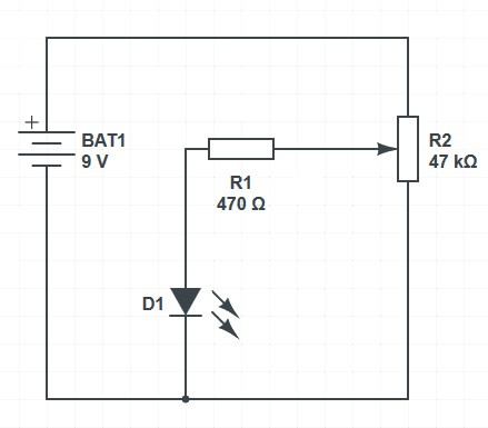
For our 2nd experiment we are going to make an LED light up but with the added extra that we can make this dimmable. For this experiment we are going to need an LED, the breadboard, some jumper cables, the 9v battery clip, a 470 Ohm resistor and a 47k variable resistor.
Variable resistors have the values wrote on the top of them.
- With the breadboard clear of all components insert the variable resistor with the two outside legs in holes j8 and j10. This will then make the centre leg of the variable resistor in pin hole i9.
- Using the left hand side red and blue strips carefully push the black wire from the battery clip into the top pin of the column with the blue stripe and the red wire from the battery clip into the top pin hole of the column with the red strip.
- Take the 470ohm resistor and connect one leg to pin hole f9 and other leg to pin hole d9
- Insert the LED positive leg, (longer leg) into c9 and the negative leg into c11
- You will need 3 jumper wires for this next step. Take one jumper wire and connect this to f8 and then into a pin hole on the positive strip. Take the 2nd jumper wire and connect this to f10 and then the other end to the negative strip. With the third jumper wire connect one pin to b11 and then the other end to the negative strip.
- Connect your battery to the battery clip.
Turn the adjuster on the variable resistor slowly clockwise and anticlockwise, you will now see that the LED can turn fully off and illuminate slowly until the LED is fully illuminated.
The 470ohm resistor we have placed in our circuit is the minimum level of resistance we need so that our LED does not blow. By adding the variable resistor in series we can increase the resistance in the circuit and limit the current flowing through the LED. By limiting the current flowing through the LED we can limit how bright the LED is.