LED Resistor Calculator
All LEDs require some form of current limiting. Connecting an LED directly to the power supply will burn it out in moments. Overdriving, even briefly, will significantly reduce it's life and light output.
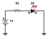
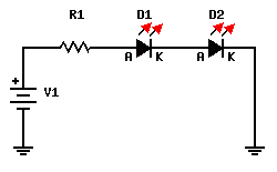
Our LED calculator will help you determine the value of the current limiting series resistor when driving a single or an array of low-current LEDs. To get started select the type of circuit for your led's, Single led - Leds in series - Leds in parallel, input the required values and hit the "Calculate" button. If you need help with the input fields please see our guide notes at the bottom of the page
If you are unsure how to identify the positive and negative off your LED see How to identify the leads of an LED


Supply voltage: Enter the voltage greater than the LED voltage drop for a single LED circuit and parallel connection or the sum of all voltage drops when connecting multiple LEDs in series.
LED current: Enter the single LED current in milliamperes. Common 3 mm and 5 mm LEDs usually operate in the range of 10-30 milliamps. A current of 20 mA is usually a safe value if you don't have access to the Led's datasheet.
LED voltage drop: The voltage drop varies greatly between different types of LEDs and also changes slightly with the current, Common 3mm led's have a typical voltage drop of 2.1 volts.
Number of LEDs: Select the number of LEDs you want to use in your circuit. This is only for LED's in series and parallel.
 An LED has two leads: a positive (anode) and a negative (cathode). On schematic diagrams, its symbol is similar to the simple diode, with two arrows pointing outwards. The anode (+) is marked with a triangle and the cathode (-) with a line. Sometimes you'll find additional labels: A or + for anode and K or - for cathode.
In most cases the longer lead is the positive (anode) and the shorter lead is the negative (cathode).

