
2 or 3 Position 2A Servo Controller MKII
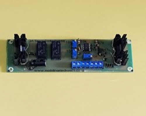
Our 2amp servo controller has been designed to control micro servos and above. This is an analog servo controller but does work with some digital servos. The board has been designed to work with servos of 180 degrees but can stretch slightly beyond that point by adjusting P2 or P3 pots on the board.
The board requires a 12v to 25v DC power supply.
The board's heat sinks do become hot when in use (Normally when servos other than micro are being used) and for this we have added a 12v DC output on the circuit to allow you to connect a cooling fan in required.
Although this is a 2 – 3 position servo controller there are only two trigger points. For example left and right. If position left and right are not triggered the servo reverts back to centre position and awaits a further trigger.
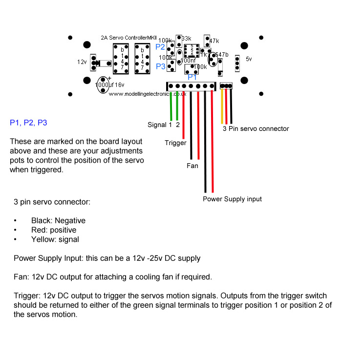
To trigger the servo you can use a two way toggle switch or two push button switches. The trigger power line, marked red on the diagram below is the power to the switch. This is then connected back to the board in either of the signal terminals, marked in green signal 1 and 2 on the diagram below.
Board Size 144mm x 45mm
Please note that PCB Pillars / Standoffs will be required for the circuit board. These fit into the 4 pre drilled holes of the circuit board. We have varies types available in our store PCB Pillars / Standoffs
Item number
Data Sheet
Product Name
Price
Add to Basket
2 or 3 Position 2A Servo Controller MKII Module Wiring Instructions
Setting the servos positions:
Note: the pots can require a number of turns in order to get the servo position to move to the desired position. If you hear a clicking noise from the pots while turning you have reached the maximum and need to turn the pot backwards.
We default set the board with centre, left 90 degrees and right 90 degrees. You will probably need to adjust these positions, which can be done following the instructions below. With no trigger position activated (Default centre position) adjust the brass screw on the blue pot marked P1 on the diagram above. By turning the screw clockwise or anticlockwise you will see the servo arm move.
In order to set position 1, connect the trigger wire via a switch and the output from the switch connects to the signal terminal 1 marked green on the diagram above. You should now see the servo move. Adjust P2 pot marked in blue on the board clockwise or anticlockwise till the servo is in the desired position.
In order to set position 2, connect the trigger wire via a switch and the output from the switch connects to the signal terminal 2 marked green on the diagram above. You should now see the servo move. Adjust P3 pot marked in blue on the board clockwise or anticlockwise till the servo is in the desired position.
To control the servo simple use the push button or toggle switch to activate the servo.