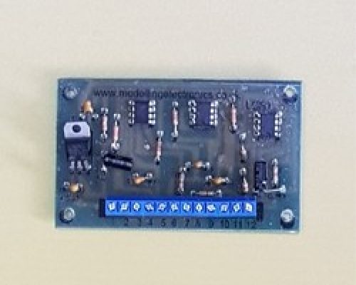
Level Crossing Simulator
Our automatic level crossing simulator circuit has been designed to give you model rail hobbyist a look off realism to their layouts. Our circuit allows you total control of when the simulator is activated (How far the trains away from the crossing) and when the simulator should stop.
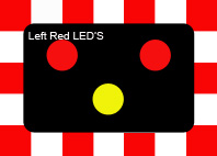
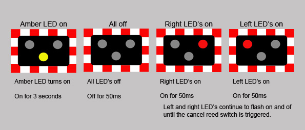
Once the train is approaching the level crossing the Amber (Yellow) LED will activate staying static for approximately 3 seconds, then the two red LED's will flash alternately until the train has passed the crossing.
The circuit is triggered by a small reed switch which is glued down into the track ballast. A small magnet is glued to the underside of the train or one of its carriages and once this magnet passed the reed switch the level crossing simulator is activated. A further reed switch is glued into the tracks ballast after the level crossing and once the train passes this reed switch the level crossing simulator circuit is cancelled and the lights stop flashing.
The circuit can handle up to four sets of level crossing lights. if all four sets are not required simply leave these out from the wring.
Input voltage should be between 9v and 20v DC only
Our kits comes in two forms, circuit only and complete pre wired kit.
Option contents: Circuit only
- Completed circuit board
- 2 x reed switches
- 1 x small 10mm x 5mm x 1mm self adhesive magnet
Option contents: Complete pre wired kit
- Completed circuit board
- 2 x pre wired reed switches
- 4 x pre wired 3mm red LED's
- 2 x pre wired 3mm yellow LED's
- 1 x small 10mm x 5mm x 1mm self adhesive magnet
We supply additional magnets in our store here: Additional magnets
Please note that PCB Pillars / Standoffs will be required for the circuit board. These fit into the 4 pre drilled holes of the circuit board. We have varies types available in our store PCB Pillars / Standoffs
Item number
Data Sheet
Product Name
Price
Add to Basket
Level Crossing Simulator Wiring Instructions
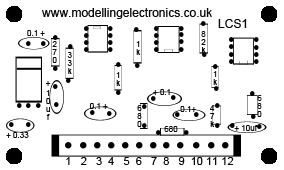
The drawing above shows a top view off our level crossing led simulator. The numbered bar on the bottom of the circuit is the PCB terminal block connection points and each numbered connection point is listed below for the correct values.
The level crossing led simulator can handle up to four sets off led's which in turn allows you to have up to four sets of lights per level crossing. Please note; each led will require a 100Ω resistor connecting to it in order to make it compatible with the 5v output from the simulator.
Input voltage should be between 9v and 20v DC only
Terminal block wiring connections
1. Positive power supply input
2. Negative power supply input
3 & 4. Trigger reed switch
5. Negative Amber (yellow) LED's
6. Positive Amber (yellow) LED's
7 & 8. Cancel reed switch
9. Negative Red LED's left side
10. Positive Red LED's left side
11. Negative Red LED's right side
12. Positive Red LED's right side
Level crossing warning lights diagram
Light Sequence
Reed switch use and placement
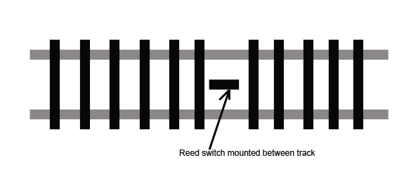
The trigger reed switch should be positioned before the level crossing, distance depends on how fast you are running your trains and how long a delay you require after your level crossing lights start flashing and the train actually arriving at the level crossing.
The cancel reed switch should be positioned after the level crossing. Again distance slowly depends on how long your train actually is. You will want to make sure all the carriages and wagons are off the level crossing before the cancel reed switch is triggered.
The reed switches we use are sub miniature and this means they are very small. In the complete kit we supply these pre-wired with black Heatshrink sleeving attached to them. because they are so small they bed into the tracks ballast pretty well even on n gauge.. We have even tested the reed switch glued on top of the n-gauge track sleepers and this has still left enough clearance for the loco.
Depending on your loco's and modelling gauge some trial and error will be required for the best positioning of your reed switches and magnets.
Magnet use and placement
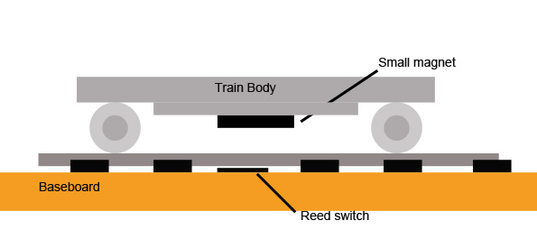
The reed switches are triggered by a small magnet that's glued to the underside of your loco or carriage/wagons. These magnets are very small and as a rule will not interfere with any parts of your loco. If you wish you can place this magnet on one of the carriages or wagons.

