Multi Point Position Indicator with Built in CDU
4 channel point position indicator with built in capacitor discharge unit for model railway point motor switching and indication.
With a built in CDU (Dual or Mega) this circuit eliminates the need for extra circuitry and from one supply can control all your point motors and LED indicators. The built in CDU provides a fast smooth DC voltage direct to your point motors to ensure smooth switching.
The Dual CDU version has virtually 10,000uf which ensures fast responsive action when switch two or more points at any one time.
The Mega CDU version has four capacitors with virtually 20,000uf which ensures fast responsive action when switching up to four points at any one time or for larger layouts were point motors and some distance away.
- Remembers points position, even after the power has been turned off
- Built in Capacitor Discharge Unit (CDU)
- Monitors up to 4 sets of points
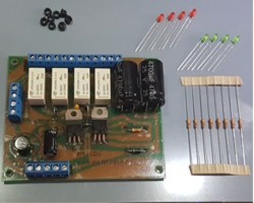
- Supplied with 4 red and 4 green led's
- 8 resistors
- PCB stand offs for mounting your circuit board safely
- Operates from 16V to 20V ac or dc
Please note that PCB Pillars / Standoffs will be required for the circuit board. These fit into the 4 pre drilled holes of the circuit board. We have varies types available in our store PCB Pillars / Standoffs
Item number
Data Sheet
Product Name
Price
Add to Basket
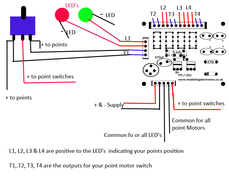
Multi Point Position Indicator with Built in CDU Wiring Instructions

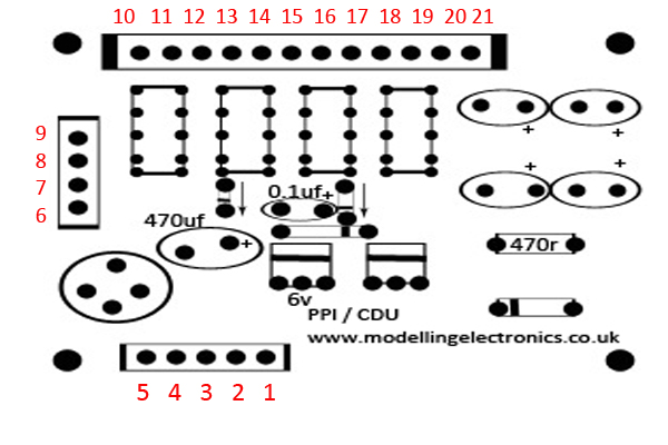
Circuit terminal connection points

- Terminal 1 is the positive supply which goes to your momentary switched supply to your point motors
- Terminal 2 is the common supply to all your point motors
- Terminal 3 is the common supply to your indicator LED’s
- Terminal 4 & 5 are the circuit power supply, this should be between 16v & 20v AC or DC. If using DC please make sure you wire the positive and negative the correct way round. Terminal 4 should be Negative and terminal 5 should be positive. If using AC polarity does not matter as the circuit will rectify the polarity for you and create a smooth DC voltage.
- Terminal 6 through to 9 are for channel 1 (1st point motor)
- Terminal 10 through to 13 are for channel 2 (2nd point motor)
- Terminal 14 through to 17 are for channel 3 (3rd point motor)
- Terminal 18 through to 21 are for channel 4 (4th point motor)
Point motor channel wiring:
channel 1 (1st point motor)
For our example we have used 1 SPDT miniature momentary toggle switch, this is a sprung switch and will revert back to the center position when released.
These switches have 3 pins; the center pin is the common positive which should be wired to your circuit at terminal 1 the positive supply for point motors.
The remaining two outputs of your switch should be wired as so:
- Switch output 1 to terminal 6 marked as T1 of the circuit board and one side of your point motor
- witch output 2 to terminal 7 marked as T1 of the circuit board and one the other side of your point motor
- Terminals 8 and 9 marked as L1 are the positive supply to your LED’s. One supply to each LED.
On the circuit board T1, T2, T3, T4 represent Triggers from your point motor switch T1 for channel 1, T2 for channel 2, T3 for channel 3 and T4 for channel 4
L1, L2, L3 L4 represent Live LED supplies for each channel
You now need to reproduce the above wiring for each channel and point motors you require switching. Please take note for each channels LED supply and triggers on the circuit wiring diagram before wiring each further channel.
Depending on the position of your points either the red LED or the Green LED will be lit.
If you need assistance in wiring the circuit please feel free to ask, our dedicated support team can assist you via email or over the phone.


