Signal Controller and Track Isolator Module
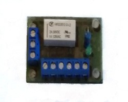
This compact signal controller with a built in track isolator has been designed to act as a double change over for when you are controlling your signals. When the signals are in the Red position the negative power to the track is isolated and the train comes to a standstill.
The signal controller can be used for any gauge model railway.
Via pins 6 and 9 the negative outputs to the track, when the signals are red power can be restored to a siding track via pin 9 and when the signal is green pin 9 is isolated and pin 6 becomes active restoring power to the main line track.
This Module is pre assembled, tested and made from high quality FR4 board.
The Module has a yellow LED on board which is lit when the module is powered and the signals are red. When power to the module has been disconnected the module remembers its current state for when power is reapplied.
The circuit can be triggered either by a toggle switch (on) off (on), push button switches (Push to make) or reed switches in the track so that when a train crosses the read switch the signals are triggered. Please note that the relays should only have a momentary trigger to switch, so a toggle switch should be sprung on
The track isolator is optional and this does not need to be wired in order for the circuit to work. If you require the track to be isolated while the signals are switched then please connect this feature.
Please note that PCB Pillars / Standoffs will be required for the circuit board. These fit into the 4 pre drilled holes of the circuit board. We have varies types available in our store PCB Pillars / Standoffs
Item number
Data Sheet
Product Name
Price
Add to Basket
Signal Controller Wiring Instructions
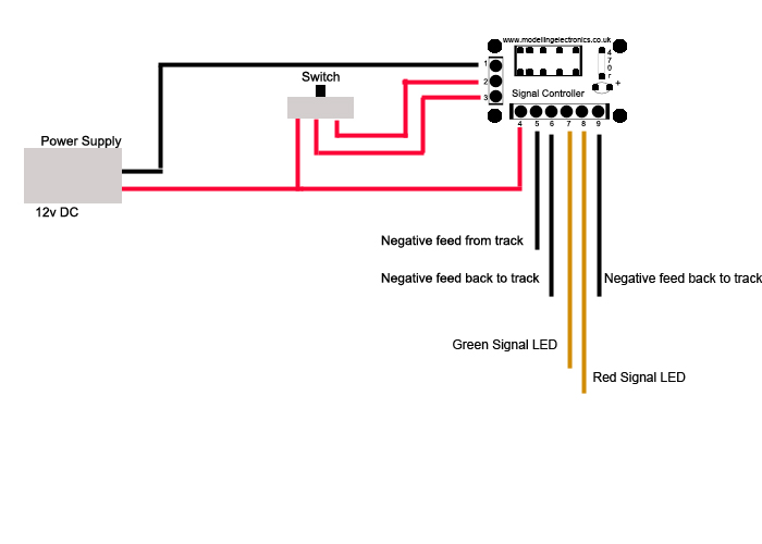
To wire the Signal Controller and track isolator circuit please make sure you have resistors connected to your Signal LED's for use up to 12v, a 560 ohm resistor should be connected if you don't already have them attached.
- Pin 1 12v supply negative input, common for signals
- Pin 2 trigger switch 1 back to board
- Pin 3 trigger switch 2 back to board
- Pin 4 12v+ supply input and 12v+ to trigger switches
- Pin 5 negative feed from the track
- Pin 6 negative feed, back to the track depending on signal position
- Pin 7 Green signal LED positive
- Pin 8 Red signal LED positive
- Pin 9 negative feed, back to the track depending on signal position
If two signals are being used you can connect a green and red signal wire (One from each signal) to pin terminal 7 and the other green and red signal wire to pin terminal 8. This will give you a green signal light on one direction and the other direction will have red signal light.
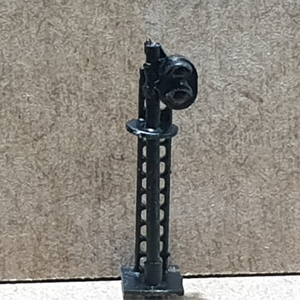
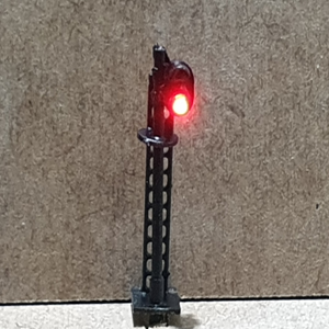
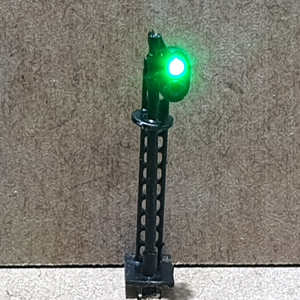
Our N Gauge 2 aspect green over red signal lights are wired with a common cathode (- Negative) specifically to work with our circuits. The signal lights come pre-wired with three wires. Height = 35mm. Their wiring instructions are below.
- Black, common negative
- Red, positive red light
- Green, positive green light
