
Using LED's in a circuit
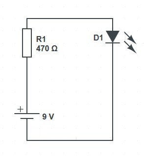
For our this experiment we are going to make an LED light up. For this experiment we are going to need an LED, the breadboard, some jumper cables for the breadboard, the 9v battery clip and a 470ohm Resistor.
The Resistor banding will be yellow, violet, brown and gold. If we use the Resistor colour chart on the back page we can see that gold is a tolerance so we need to start reading from yellow.
Yellow = 4 Violet = 7 and are multiplier is x101
When using x10 (to the power of), for resistor calculations all we need to do is add a zero depending on the power of, so in our case we have 47x101 so this will be 470 which is a 470 Ohm Resistor.
LED’s need to be connected into the circuit the correct way, these are polarity sensitive, which means they will only work if the positive and negative are connected the right way round.
If you look at the legs on the LED you will see one leg is slightly longer than the other, the longer leg is the positive side of the LED.
Another way to check which leg is positive and which is negative is to hold the LED up to the light. When doing this you will see two shapes inside the LED dome like the image to the right.
This will allow you to work out which way round the LED should go if the legs have been cut.
- Place the breadboard down on a flat surface; you will see that there are vertical rows on each side with red and blue stripes. You will also see that there are numbers 1-30 and columns a-j. Place your breadboard so that row 1 is at the top.
- Using the left hand side red and blue strips carefully push the black wire from the battery clip into the top pin of the column with the blue stripe and the red wire from the battery clip into the top pin hole of the column with the red strip.
- Take the 470ohm Resistor (yellow, violet, brown, gold) place one side of the resistor in row 4 of the red track and the other side into a4.
- Take your LED and push the long leg into b4 and the short leg into b5.
- Take a short jumper wire and place one side in to a hole on the blue strip and the other side into c5.
- Connect the 9v battery to your battery clip.
Your LED should now light up
Electricity is now flowing from the battery through the resistor and then through the LED. The resistor is limiting the amount of flow and reduces the current to a safe level. Without the resistor the LED would consume as much current as the battery would give. This would cause the LED to get very hot and pop.
Remove the battery and then the jumper wire from the breadboard and take a diode from your components.
A diode has a grey stripe at one end. The leg with the grey strip at the end should be placed in hole c5 and then connect the other end of the diode to the negative (Blue) strip on your breadboard.
Reconnect your battery to the bread board.
What happens?
Your LED should not light up. Disconnect the battery and remove the diode and then insert the diode back into the breadboard the opposite way around. The leg with the grey stripe should be inserted into the negative strip and the other leg into c5.
Reconnect the battery and the LED will light up.
In the short description of what’s included we said that diodes allow electricity to flow in one direction only. Electrons flow from negative to positive. When a power source is connected to a diode, the Batteries positive power source on the anode and the negative on the cathode (the side of the diode with the grey stripe), the diode becomes a conductor and allows current to flow through the diode.