
Rain Detector Circuit
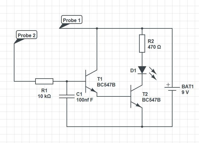
For your 3rd experiment we are going to make a rain detector circuit. This circuit can also be used as a leak detector circuit and is used sometimes in model boats to alert the user that their boat has a leak in the hull.
For this experiment we are going to introduce transistors. Transistors can be used in a circuit in three different configurations; the most common mode is the common emitter configuration or CE for short. This means the emitter terminal of the transistor is common in both input and the output of the circuit.
D1 which is your LED can be substituted for a buzzer, if this was done R2, (which is the resistor that limits the current flow to safe levels for our LED,) would not be required.
For this experiment the probes can be substituted for some longer jumper wires, these will produce the same result. In model boats the probes are just thin solid wire glued 5mm apart.
For this experiment we are going to need an LED, the breadboard, some jumper cables, the 9v battery clip, 2 BC547B transistors, a 100nf ceramic disc capacitor, a 470 Ohm Resistor and a 10k Ohm Resistor.
- With the breadboard clear of all components we need to insert the transistors into the board. These need to be inserted the correct way round. You will notice that one side of the transistor is flat. Looking at the image below we can see which pin is the collector, base and emitter. Transistors can have different pin configurations and you should always check.
- Using the first transistor, insert the collector, base and emitter into the following pin holes on your breadboard:-
- Collector into pin hole D14
- Base into pin hole C15
- Emitter into pin hole D16
- The second BC547B transistor needs to be inserted into the following pin holes on your breadboard.
- Collector into pin hole H14
- Base into pin hole G15
- Emitter into pin hole H16
- Using the left hand side red and blue strips carefully push the black wire from the battery clip into the top pin of the column with the blue stripe and the red wire from the battery clip into the top pin hole of the column with the red strip.
- The negative leg (Short leg) of your LED needs to be connected to pin hole i14 and the positive leg to i12
- Take your 470 Ohm resistor and insert one leg to pin hole j12 and the second leg to j8
- Your 10k Ohm resistor needs to be inserted with one leg into pin hole a15 and the second leg into pin hole a10
- Your ceramic disc 100nf capacitor is none polarised so either leg can be connected into pin hole b15 and the second leg into b17
We now have all our components inserted into our breadboard this is a good time to check over the circuit drawing and make sure all our components are inserted into the correct pin holes.
- Using short jumper wires connect one jumper wire to pin hole i8 and the other end to the positive strip on the left hand side.
- Using a short jumper wire connect one wire to pin hole e14 and then the other end into the positive strip on the left hand side.
- Using a short jumper wire connect one wire to pin hole e16 and the other end to pin hole f15.
- Using a short jumper wire connect on wire to pin hole to c17 and then the other end into a pin hole on the negative strip on the left hand side.
- Using a short jumper wire connect one wire to pin hole i16 and then the other end to a pin hole to the negative strip on the left hand side.
- Taking a long jumper wire connect one end to pin hole b10, the other end of this jumper wire will be our probe 2.
- Taking a long jumper wire connect one end to a pin hole on the positive power strip. The other end of this wire will be our probe 1.
- Connect your 9v battery to the battery connector.
You can quickly test your circuit to make sure it works by touching the end of probe 1 and probe 2 together, your LED should now light up.
If the led now lights up your circuit is working and it’s time to test it with water. Water conducts electricity so as long as the two ends of the probes are close enough together a small droplet of water is enough to activate the detector.
You can test your circuit with a small dish or capful of water.
This circuit has many uses and can be modified to add a buzzer or to use a 12v power source such as a transformer. Additional uses of this circuit could be for a fish tank to alert the owner if a leak had started so that measures could be taken before too much damage was done. Multiple probes can be connected to the circuit and placed in various places to detect for leaks in a larger area.