
Electronics Project Circuits
Welcome to our projects section. We have created the tutorials here to expand the circuits in our Electronics Starter Kits, most of the circuits you can build with the components supplied in the starter kits, while some circuits will require a few additional components.
All the circuits come with a step by step guide and a downloadable PDF sheet, this allows you to quickly expand the booklet supplied with the Electronics Starter Kit.
Rain Detector Circuit
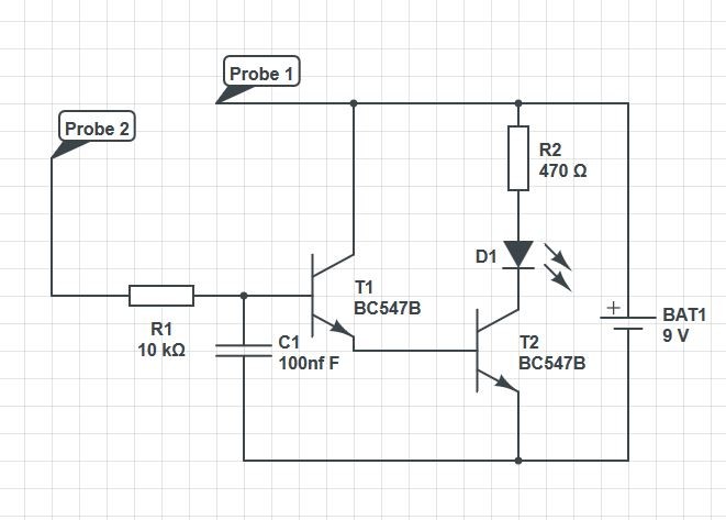
For your 3rd experiment we are going to make a rain detector circuit. This circuit can also be used as a leak detector circuit and is used sometimes in model boats to alert the user that their boat has a leak in the hull.
For this experiment we are going to introduce transistors. Transistors can be used in a circuit in three different configurations; the most common mode is the common emitter configuration or CE for short. This means the emitter terminal of the transistor is common in both input and the output of the circuit.
D1 which is your LED can be substituted for a buzzer, if this was done R2, (which is the resistor that limits the current flow to safe levels for our LED,) would not be required.
For this experiment the probes can be substituted for some longer jumper wires, these will produce the same result. In model boats the probes are just thin solid wire glued 5mm apart.
For this experiment we are going to need an LED, the breadboard, some jumper cables, the 9v battery clip, 2 BC547B transistors, a 100nf ceramic disc ... more
Dimmable LED
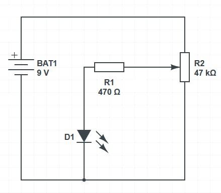
For our 2nd experiment we are going to make an LED light up but with the added extra that we can make this dimmable. For this experiment we are going to need an LED, the breadboard, some jumper cables, the 9v battery clip, a 470 Ohm resistor and a 47k variable resistor.
Variable resistors have the values wrote on the top of them.
- With the breadboard clear of all components insert the variable resistor with the two outside legs in holes j8 and j10. This will then make the centre leg of the variable resistor in pin hole i9.
- Using the left hand side red and blue strips carefully push the black wire from the battery clip into the top pin of the column with the blue stripe and the red wire from the battery clip into the top pin hole of the column with the red strip.
- Take the 470ohm resistor and connect one leg to pin hole f9 and other leg to pin hole d9
- Insert the LED positive leg, (longer leg) into c9 and the negative leg into c11
- You will need 3 ... more
Using LED's in a circuit
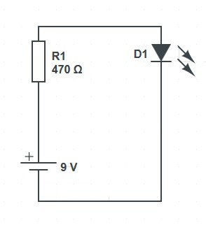
For our this experiment we are going to make an LED light up. For this experiment we are going to need an LED, the breadboard, some jumper cables for the breadboard, the 9v battery clip and a 470ohm Resistor.
The Resistor banding will be yellow, violet, brown and gold. If we use the Resistor colour chart on the back page we can see that gold is a tolerance so we need to start reading from yellow.
Yellow = 4 Violet = 7 and are multiplier is x101
When using x10 (to the power of), for resistor calculations all we need to do is add a zero depending on the power of, so in our case we have 47x101 so this will be 470 which is a 470 Ohm Resistor.
LED’s need to be connected into the circuit the correct way, these are polarity sensitive, which means they will only work if the positive and negative are connected the right way round.
If you look at the legs ... more